 Jiangsu Shendian Electric Co., Ltd.
Quick Answer
A 250 kVA 11 kV oil-immersed transformer for a renewable project is a hermetically sealed three-phase unit that steps inverter or turbine output up from 0.4 kV — 0.69 kV on wind — to 11 kV for the grid connection, and back down to 400/230 V when the site runs in island mode. It suits a 200–250 kWp PV array, a single medium wind turbine or a hybrid mini-grid. Because it stays energised 8,760 hours a year while the plant produces at a 12–20% capacity factor, no-load loss is about 65% of the annual energy lost. Specify GB 20052-2024 Class 1 (S22-M-250/11, 220 W no-load), Dyn11 and a sealed corrugated tank.
Product Overview
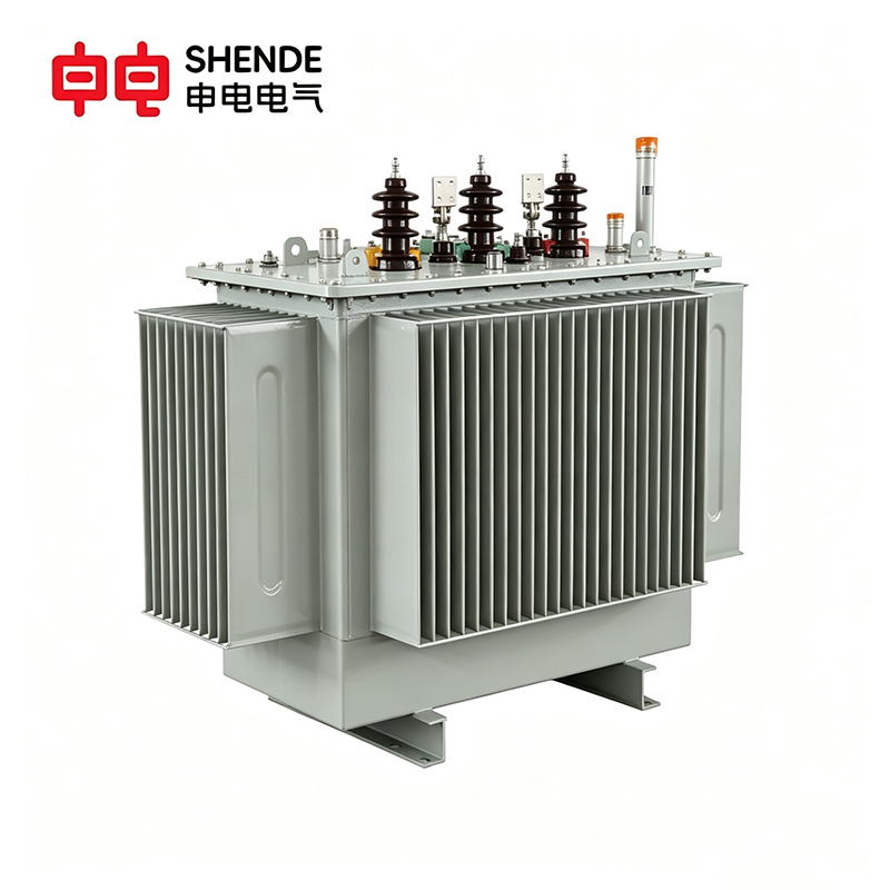
This is a three-phase, 50/60 Hz ONAN oil-immersed transformer rated 250 kVA with an 11 kV and a 0.4 kV winding — 0.69 kV for wind turbines and 0.8 kV for a 1500 V PV system — used in either direction: stepping inverter or turbine output up to 11 kV for export, or 11 kV down to 400/230 V when the site runs as an island. Both windings are copper, sealed in a corrugated-fin tank with no conservator, so the oil never contacts air and needs no sampling or filtration over a 25-year design life. Oil temperature monitoring with alarm and trip contacts plus RS485/Modbus RTU are standard, with optional 4G or LoRa DTU. Tested to IEC 60076-1/-2/-3/-5/-10, wind duty to IEC 60076-16, energy performance to GB 20052-2024.
What GB 20052-2024 Changed for Renewable-Duty Transformers
China’s GB 20052-2024 took effect on 1 February 2025 and, for the first time, brings photovoltaic, wind and storage transformers from 6 kV to 35 kV into the mandatory efficiency scheme, expanding the tables from 28 to 42 categories. Grades are NX1 (best), NX2 and NX3 — S22, S20 and S13 on silicon steel; SBH25, SBH21 and SBH15 on amorphous cores. For an overseas buyer the value is that the grade is verifiable against a type test report, and that Class 1 here comfortably meets EU Ecodesign Tier 2.
Why Solar and Wind Sites Choose Sealed Oil-Immersed Over Dry Type
Our recommendation: for an outdoor PV array, wind cluster or hybrid mini-grid, specify a hermetically sealed oil-immersed transformer; keep cast resin dry type for indoor rooms, plateau sites above roughly 3,000 m, and where the fire or environmental code rules out mineral oil.
Why oil wins here: 220 W no-load loss against higher dry-type figures, no night-time condensation in a sealed tank, oil mass absorbing cloud transients and gust peaks, and IP54 cable boxes that stand in the open without a room.Where oil loses: near forest or a water catchment, use dry type or natural ester; above roughly 3,000 m, use dry type.
Silicon Steel or Amorphous Core at 250 kVA
250 kVA is where amorphous starts to pay, and renewable duty favours it: the core cuts no-load loss from 220 W to ≈110 W, while load loss rises slightly to ≈2,400 W and first cost typically runs 15–30% higher. Decision rule, not a payback claim: on PV duty it saves about 18,600 kWh over 20 years against S22 — roughly USD 2,240 at USD 0.12/kWh. Take it if the quoted premium is below that figure; otherwise stay with S22. Loss and running-cost figures sit beside the silicon-steel grades in the table below.
Energy Efficiency Grades and the 20-Year Running Cost
On a renewable site the transformer is energised far longer than the plant produces — a PV array runs at a 12–20% capacity factor while the transformer sits on 11 kV for all 8,760 hours of the year — so the no-load figure, not the purchase price, decides the 20-year cost.
| GB 20052-2024 Grade | Model | No-load loss P0 | Load loss Pk (75 °C) | Annual loss – PV duty | Annual loss – wind duty | 20-yr cost – PV | 20-yr cost – wind |
| Class 3 (NX3) | S13-M-250/11 | 290 W | 3,200 W | ≈ 3,980 kWh | ≈ 5,702 kWh | ≈ USD 9,553 | ≈ USD 13,685 |
| Class 2 (NX2) | S20-M-250/11 | 260 W | 2,560 W | ≈ 3,430 kWh | ≈ 4,807 kWh | ≈ USD 8,231 | ≈ USD 11,537 |
| Class 1 (NX1) | S22-M-250/11 | 220 W | 2,330 W | ≈ 2,976 kWh | ≈ 4,229 kWh | ≈ USD 7,142 | ≈ USD 10,150 |
| Class 1 amorphous | SBH25-M-250/11 | ≈ 110 W | ≈ 2,400 W | ≈ 2,044 kWh | ≈ 3,335 kWh | ≈ USD 4,905 | ≈ USD 8,004 |
Moving from Class 3 to Class 1 saves about 20,100 kWh over 20 years on a PV site and 29,500 kWh on a wind site — roughly USD 2,410 and USD 3,535 at USD 0.12/kWh. On PV duty no-load loss alone is about 65% of the annual total, so improving load loss alone is the wrong lever here.
Grid-Connected vs Off-Grid: What Changes
The transformer itself is bidirectional and needs no change between the two modes. What changes is the earthing, the protection scheme and, on weak feeders, the tapping range.
| Item | Grid-connected (grid-tied) | Off-grid / island |
| Power flow | 0.4 kV → 11 kV, export to the utility | Both directions: 0.4 → 11 kV by day, 11 → 0.4 kV for site loads |
| Neutral and earthing | As the utility requires | LV neutral must be earthed (TN-S or TT) — Dyn11 provides it |
| Tapping range | ±2×2.5% normally sufficient | Wider range or OLTC if island voltage swings |
| Short-circuit level | Utility contributes fault current | Inverters only — low; Uk% affects protection sensitivity |
| Night behaviour | Idle, no-load loss only | May be switched off with the island |
Sizing: What Array and Inverter Does 250 kVA Match?
Match the transformer to inverter AC output, not array size: kVA ≈ inverter AC kW ÷ 0.9, so 250 kVA covers about 225 kW of inverter capacity — with the usual 1.1–1.2 DC/AC oversizing, a 250 kWp array, typically eight to ten 25–30 kW string inverters on one LV board, a single 225 kW central inverter, or a PV + battery + genset block.
Key Features
- Dual-direction by design — 0.4 kV to 11 kV for export and 11 kV to 400/230 V for island loads in one unit; Dyn11 traps triplen harmonics and gives island loads a neutral.
- Low no-load loss for renewable duty — 220 W against 290 W for Class 3, about 65% of annual losses on PV duty. GB 20052-2024 Class 1 (NX1) as standard, under the renewable-duty category the 2024 edition introduced for PV, wind and storage transformers from 6 kV to 35 kV; type test report provided. Amorphous SBH25 core optional, cutting no-load loss by roughly half.
- Sealed corrugated tank, no conservator — no oil sampling or filtration over the 25-year design life, no moist air drawn in overnight, and enough thermal mass to smooth cloud transients and gust peaks.
- Inverter-ready — copper windings both sides for lower loss and better short-circuit withstand (IEC 60076-5), designed for harmonic current per IEEE 519 / IEC 61000-3-12 and IEEE C57.110 and for DC injection; natural ester option, readily biodegradable, fire point above 300 °C.
- Harsh sites and remote monitoring — C4 / C5-M coating for coastal and desert duty, high-altitude design above 1,000 m, -25 °C to +40 °C ambient with -40 °C and +50 °C versions; oil and winding temperature, load current and voltage on RS485/Modbus RTU, with optional 4G or LoRa DTU.
Typical Applications
- Commercial and industrial rooftop or ground-mount PV arrays of roughly 200–250 kWp feeding an 11 kV feeder
- Single medium wind turbines and small wind clusters with 690 V generator output
- Hybrid PV + battery + diesel mini-grids for villages, farms, ranches, mines and telecom sites
- Off-grid islands, mining camps, irrigation stations, solar-plus-storage microgrids and weak-grid or long-feeder connections
Standards and Certifications
Designed and tested to IEC 60076-1/-2/-3/-5/-10 and IEC 60076-16 (wind), plus GB 1094 and GB/T 6451. Energy performance meets GB 20052-2024 Class 1 (NX1) — Class 2 (NX2) with the S20 design — under the renewable-duty category; inverter harmonic duty per IEEE C57.110, IEEE 519 and IEC 61000-3-12. Manufactured under ISO 9001, ISO 14001 and ISO 45001; CE conformity and third-party type test reports (CNAS-accredited, KEMA or equivalent) available on request.
WeChat
Scan the QR Code with wechat