 Jiangsu Shendian Electric Co., Ltd.
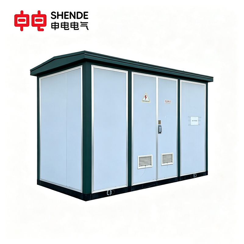
Selecting a transformer for a commercial, industrial, or utility project involves more than choosing the correct voltage and capacity. Buyers must also consider installation space, electrical safety, equipment integration, maintenance access, and environmental protection. Traditional transformer installations often require separate equipment enclosures and additional site work, which increases installation complexity and project cost. A box-type transformer offers an integrated alternative, but understanding its construction, operating principle, advantages, and limitations is essential before deciding whether it fits the project.
A box-type transformer is an integrated electrical substation assembly that typically combines a transformer, medium-voltage switching or protection equipment, and low-voltage distribution equipment within one or more enclosed compartments. It transforms voltage and distributes power in a compact, organized installation. Depending on the design and regional terminology, the term may include prefabricated substations and compact substations, in configurations used in residential developments, commercial buildings, industrial facilities, renewable-energy projects, and distribution networks. Because specifications vary considerably by design and application, buyers should understand the internal configuration, insulation and cooling method, protection features, accessibility, and applicable standards before selecting a unit.
1. What Is a Box-Type Transformer and How Does It Work?
A box-type transformer is a compact power distribution unit that integrates a transformer with an enclosure and, depending on its design, medium-voltage switching equipment, protection devices, and low-voltage distribution components. It converts power from one voltage level to another through electromagnetic induction while providing an enclosed, organized installation, in settings ranging from commercial buildings and industrial plants to residential communities and renewable-energy systems.
1.1 What Is Included in the Enclosure?
Unlike a transformer supplied as a standalone piece of equipment, a box-type transformer may combine several electrical functions within one enclosure: a transformer core and windings; a medium-voltage compartment with switches, fuses, or load-break switches; a low-voltage compartment with circuit breakers, busbars, metering equipment, and outgoing connections; a protective enclosure rated against accidental contact and environmental exposure; a cooling system; and monitoring devices such as temperature indicators, pressure-relief devices, and alarms.
Not every box-type transformer includes all of these features. Some products contain only the transformer and its enclosure, while others are complete packaged substations. Buyers should therefore confirm the actual equipment scope rather than relying on the product name alone.
1.2 The Operating Principle
The operating principle is the same as that of any conventional transformer: electromagnetic induction. When alternating current flows through the primary winding, it produces a changing magnetic flux in the core, and this changing flux induces a voltage in the secondary winding. The voltage ratio approximately equals the turns ratio (Vp / Vs ≈ Np / Ns), where Vp and Vs are the primary and secondary winding voltages and Np and Ns are the respective winding turns. For example, a distribution transformer may reduce medium voltage to a lower voltage suitable for a building’s distribution system; the actual levels depend on the supply network and equipment requirements.
In practice, power flows through the unit in a clear sequence. Electrical energy enters through the designated medium-voltage connection; where included, switching devices and protective equipment provide isolation and fault protection; the primary winding, magnetic core, and secondary winding transfer energy by electromagnetic induction and change the voltage level; and the secondary output feeds the low-voltage distribution compartment or downstream switchgear, delivering electricity to connected equipment, lighting, motors, and other loads.
One practical caution: a transformer’s secondary voltage varies with load current, winding impedance, tap position, and the incoming supply voltage. The rated voltage ratio should not be interpreted as a guarantee of perfectly constant output voltage under every operating condition.
2. What Are the Main Components of a Box-Type Transformer?
The exact configuration depends on the rated voltage, capacity, cooling method, insulation system, and whether the product is a standalone enclosed transformer or a complete packaged substation.
2.1 Transformer Core and Windings
The core provides a controlled magnetic path for the alternating flux linking the windings. It is commonly built from thin, insulated electrical-steel laminations designed to reduce eddy-current losses, in either a core-type or shell-type arrangement. Core material, lamination quality, joint design, and magnetic flux density all influence performance. The operating frequency and voltage must match the design to prevent overheating.
The windings are the conductive coils that transfer energy between voltage levels, commonly made from copper or aluminum depending on design, cost, and performance requirements. The primary winding receives energy from the incoming supply, while the secondary winding delivers the transformed energy to the load. The actual terminal voltage also depends on winding resistance, leakage reactance, load current, and tap position, and in three-phase transformers the winding connections must be considered when comparing line-to-line voltages with turns ratios. Key specifications include conductor material and cross-section, insulation arrangement, rated current, short-circuit withstand capability, and temperature-rise limits.
2.2 Insulation System
The insulation system separates energized conductors from one another and from grounded components, withstanding normal operating voltage, switching surges, and other specified electrical stresses. In an oil-immersed unit, insulation typically combines solid materials with insulating liquid, which also transfers heat away from the core and windings; dry-type transformers rely on solid insulation and an air-based or otherwise specified cooling arrangement. Insulation reliability depends on material quality, manufacturing cleanliness, moisture control, temperature, and electrical stress, so buyers should review the specified insulation level and test requirements rather than assuming all products share the same design.
2.3 Cooling System
Transformer losses generate heat in the core, windings, and other conductive parts. If heat is not removed effectively, insulation aging accelerates and service life shortens. Oil-immersed units transfer heat through the insulating liquid to the tank and cooling surfaces, while dry-type units depend on air circulation through or around the active parts. Key factors include ambient temperature and altitude, expected load profile and overload requirements, ventilation around the enclosure, the condition of radiators or cooling surfaces, and exposure to dust and moisture.
2.4 Protective Enclosure
The enclosure houses and protects the internal equipment, providing the required mechanical protection and environmental resistance. A complete assembly may contain separate compartments for the medium-voltage equipment, the transformer, and the low-voltage distribution equipment, which helps organize cable connections and improve maintenance access. The enclosure does not replace proper electrical isolation, grounding, or safe working procedures; its material, dimensions, ventilation, and protection rating must match the actual site environment and project requirements.
2.5 Medium-Voltage Switching and Protection Equipment
In a complete packaged substation, the medium-voltage compartment receives incoming power and may include load-break switches, fuses, circuit breakers, disconnectors, and associated relays or control devices, each rated for its switching or fault-interruption duty. These components are not present in every box-type transformer, and protection must be coordinated with the transformer rating, upstream supply, downstream equipment, and available fault current. The mere presence of a component does not guarantee that the overall system is adequately protected.
2.6 Low-Voltage Distribution Equipment
The low-voltage compartment receives power from the transformer’s secondary side and distributes it to downstream circuits. It may contain a main circuit breaker, feeder breakers, busbars, metering instruments, current transformers, and cable termination points, with busbars carrying current between internal components and protective devices controlling or interrupting circuits according to their ratings. Important selection criteria include the rated secondary voltage and current, main and feeder circuit ratings, short-circuit withstand requirements, busbar capacity, cable sizes and terminations, required metering functions, and the space available for inspection and maintenance. A suitable transformer rating alone is not enough if the associated switchgear and outgoing circuits are undersized.
2.7 Grounding System and Safety Accessories
The grounding system connects designated conductive parts to the installation’s grounding network, establishing an appropriate fault-current path and supporting the operation of protective devices. Other accessories may include temperature indicators, pressure-relief devices, liquid-level indicators, alarms, and protective interlocks, which are particularly relevant to oil-immersed designs and complete packaged substations. Buyers should verify sensor types, alarm functions, and interlock logic, and should specify these accessories as part of the complete installation design rather than as optional details added after equipment selection.
2.8 How the Components Work Together
These components form an integrated power distribution system. Incoming power reaches the primary winding through the designated connection and, where provided, the medium-voltage switching and protection equipment. The core transfers alternating flux between the windings and induces the required secondary voltage. The insulation system keeps energized parts separated, the cooling arrangement removes heat, the enclosure protects and organizes the equipment, and the low-voltage compartment distributes power to outgoing circuits, with grounding, monitoring, and protection equipment supporting safe operation throughout. This explains why selection should consider the complete assembly rather than the transformer alone: incompatible switching equipment, inadequate cooling, incorrect winding connections, or insufficient short-circuit capability can undermine an otherwise suitable transformer.
3. What Are the Common Types of Box-Type Transformers?
Box-type transformers are available in different designs to meet distribution and installation needs, and choosing the wrong type can lead to unnecessary installation costs, poor space utilization, inadequate protection, or compatibility problems with the existing network. Because products differ in enclosure design, cooling method, voltage configuration, and equipment arrangement, comparing them by appearance or rated capacity alone can result in an unsuitable purchase.
3.1 Oil-Immersed Box-Type Transformers
Oil-immersed units use insulating liquid around the core and windings to provide electrical insulation and transfer heat to the cooling surfaces. A typical configuration adds radiators or other heat-dissipation surfaces, high- and low-voltage bushings or cable interfaces, an external protective enclosure, and optionally medium-voltage switching and low-voltage distribution compartments with monitoring accessories. Liquid-based cooling can support compact designs at suitable ratings, which makes these units attractive for outdoor distribution networks, industrial facilities, and commercial developments. However, buyers must consider liquid containment, leakage prevention, fire-risk management, inspection requirements, and local environmental regulations, and the term “oil-immersed box-type transformer” does not automatically mean the product includes complete switchgear, so the manufacturer’s scope of supply should be checked carefully.
3.2 Dry-Type Box-Type Transformers
Dry-type units use solid insulation rather than an insulating-liquid-filled tank, often with cast-resin windings or other dry insulation systems, and heat removed through air circulation or a specified cooling arrangement. Dry-type designs are often considered for indoor installations, commercial buildings, public facilities, and locations with particular fire-safety or liquid-containment requirements, though suitability still depends on the insulation system, enclosure design, ventilation, environmental conditions, and applicable codes. A dry-type transformer should not be assumed to be maintenance-free or suitable for every indoor environment: dust, humidity, contamination, restricted airflow, and high ambient temperature can all affect reliability.
3.3 Packaged Box-Type Substations
A packaged substation is an integrated assembly that combines a transformer with designated medium- and low-voltage equipment within a coordinated enclosure or set of compartments. In some markets, the term “box-type transformer” is used broadly to describe this complete distribution unit. A common configuration has three functional sections: a medium-voltage compartment with incoming switching equipment, fuses, circuit breakers, or other protection and isolation devices; a transformer compartment housing the oil-immersed or dry-type transformer; and a low-voltage compartment with the main distribution equipment, busbars, outgoing feeders, and specified metering or monitoring devices. Packaged substations are commonly used in residential developments, commercial buildings, industrial parks, infrastructure projects, and distribution networks.
3.4 Solar and Wind Power Box-Type Transformers
Solar power projects use box-type transformer assemblies to collect power from inverter systems and raise the voltage for connection to a collection network or grid interconnection point. A typical configuration includes a transformer rated for the project’s inverter output and operating profile, medium-voltage switching and protection equipment, low-voltage connections from the inverter outputs, monitoring interfaces, and an enclosure designed for outdoor installation. The design must match the inverter output voltage, transformer capacity, grid connection voltage, grounding arrangement, and applicable interconnection requirements, and engineers should also evaluate harmonics, ambient temperature, dust, humidity, and any specified overload requirements.
Wind power applications similarly use box-type transformers to raise the voltage generated by a turbine or to connect turbine output to a collection network, with a transformer matched to the generator or converter output, medium-voltage connections to the collection network, designated switching and protection equipment, temperature monitoring, and an enclosure suited to the environmental conditions. Wind installations experience temperature variation, vibration, humidity, dust, and challenging maintenance access, so selection should account for the actual location and operating conditions rather than rated capacity alone. A wind power transformer is not a unique transformer technology; it may be an oil-immersed or dry-type design selected for the application.
3.5 Industrial and Urban Distribution Configurations
Industrial facilities and urban distribution systems require configurations built around the site’s available space, load profile, incoming network, and downstream distribution arrangement. Industrial applications need additional attention to motor starting, harmonic-producing loads, short-circuit levels, protection coordination, and future load expansion, while urban installations emphasize footprint, noise, access, enclosure protection, and integration with surrounding infrastructure. Common configurations range from a transformer-only enclosure, through a transformer with medium-voltage switching equipment, to a complete packaged substation with low-voltage distribution equipment.
3.6 Comparing Configurations and Choosing the Right Type
These categories overlap rather than exclude one another: a packaged substation may contain an oil-immersed transformer, and a solar installation may use a compact oil-immersed assembly with dedicated monitoring. Beyond transformer technology, products also differ in how components are arranged and accessed. Options range from a transformer-only enclosure, through integrated medium-voltage arrangements that coordinate the incoming switching with the transformer connection, to fully integrated packaged substations that reduce site assembly, plus special-purpose designs adapted to renewable-energy collection, restricted space, or unusual environments; in each case the buyer must confirm the complete supply scope, access, clearances, and test documentation. Integration can simplify project coordination, but it does not eliminate the need for suitable foundations, cable installation, grounding, commissioning, and safe working clearances.
The best configuration meets the electrical and environmental requirements without adding unnecessary complexity or cost. Buyers should confirm the rated capacity, voltages, frequency, phase configuration, winding connections, and load profile; decide between oil-immersed and dry-type construction and between a transformer-only supply and a complete packaged substation; then assess short-circuit requirements, impedance, insulation level, cooling, enclosure protection, corrosion exposure, and maintenance access, confirming inverter or generator compatibility for solar and wind applications. Finally, request a datasheet, outline drawing, connection diagram, equipment list, and factory test documentation so that clear specifications avoid gaps between the manufacturer, switchgear supplier, installation contractor, and commissioning team.
4. What Are the Advantages and Limitations of a Box-Type Transformer?
Choosing a box-type transformer can simplify power distribution projects, reduce installation complexity, and help protect electrical equipment. However, an unsuitable configuration may create problems with cooling, maintenance access, fault protection, or future capacity expansion, and focusing only on the compact design or the initial purchase price can lead to unexpected costs over the transformer’s service life.
4.1 Main Advantages
The principal advantage is integration, and it expresses itself in several ways. First, compact design and efficient space utilization: the transformer and its associated equipment are organized within a coordinated enclosure, reducing the need for separate equipment structures and making better use of limited space, which is especially valuable in urban networks, commercial developments, industrial parks, and renewable-energy facilities—provided the enclosure still offers sufficient working clearances, cable access, and ventilation.
Second, integrated equipment and simplified installation. When the required components are factory-assembled, installation teams benefit from a coordinated layout, fewer separate interfaces, more organized cable routing, better coordination between the transformer and its switchgear, and more predictable installation planning. Factory integration does not eliminate site preparation, cable termination, grounding, commissioning, or acceptance testing, so buyers should verify the exact scope of supply and know which tasks remain the contractor’s responsibility.
Third, protection against environmental exposure. The enclosure shields internal components from environmental conditions and accidental contact according to its specified rating, and may include corrosion-resistant coatings, weather-resistant construction, ventilation provisions, secure access doors, and designated cable entry points. The actual protection level depends on enclosure design, sealing, ventilation, installation quality, and maintenance.
Fourth, organized compartments and operational safety. In a packaged-substation configuration, equipment is installed in separate compartments by function and voltage level, making connections and maintenance areas easier to identify. Safety features such as locks, interlocks, barriers, warning labels, and controlled access points support safe operation but do not replace isolation procedures, lockout/tagout practices, voltage verification, or proper grounding during maintenance.
Finally, application flexibility. Box-type transformers can be configured for commercial buildings, industrial facilities, residential communities, urban networks, solar and wind plants, and infrastructure projects, with different ratings, voltage ratios, cooling methods, and monitoring options, though not every design suits every application.
4.2 Main Limitations
The same compactness that makes box-type transformers attractive also creates constraints. Restricted internal space can limit access to internal components: inspecting or replacing a particular part may require removing covers, disconnecting cables, or coordinating work across several compartments. Buyers should review the outline drawing, access-door arrangement, component-removal path, and required clearances before purchase, especially if frequent switching changes or future equipment additions are expected.
Cooling and ventilation are the second constraint. In a compact enclosure, restricted airflow, blocked ventilation openings, high ambient temperatures, or inadequate clearance around radiators reduce cooling effectiveness, and excessive operating temperature accelerates insulation aging and shortens service life. Buyers should evaluate ambient temperature, altitude, load profile, ventilation, and solar exposure, and should not assume that two transformers with the same kVA rating have identical thermal performance.
Third, maintenance and component replacement can be more involved. Consolidating equipment simplifies routine inspection, but replacing a switching device, modifying cable connections, or upgrading a distribution panel may require additional planning and downtime, depending on the layout and whether the equipment is designed for modular replacement. A suitable maintenance strategy should address access, isolation points, spare-parts availability, inspection intervals, and the manufacturer’s service support.
Fourth, expansion and modification may be limited. An integrated assembly is designed around a defined equipment arrangement, so when load grows or the protection scheme changes, there may be little space to add larger breakers, additional feeders, or new monitoring devices. Some designs allow modular upgrades; others require replacing a compartment or installing additional equipment outside the enclosure. If expansion is likely, a small initial footprint may not be the most economical option.
Finally, cost depends on the configuration. A complete packaged substation may cost more initially than a transformer supplied alone, and integrated equipment can raise replacement costs when specialized parts are unavailable. A fair comparison should include the transformer, switchgear, enclosure, foundations, cabling, installation, testing, maintenance, expected losses, and potential future upgrades; the lowest purchase price does not necessarily produce the lowest lifetime cost.
A box-type transformer is not automatically safer, more efficient, or easier to maintain than every alternative; these outcomes depend on design quality, correct installation, and operating conditions, and adequate ventilation, safe access, grounding, and protection coordination remain essential in every case.
4.3 When Is a Box-Type Transformer a Good Choice?
A box-type transformer is often a good choice when the project needs a compact, organized distribution assembly and the equipment configuration can be defined clearly before installation. It is particularly attractive where installation space is limited, where a factory-assembled solution is preferred, where the site benefits from an enclosed and coordinated arrangement, and where the required voltage, capacity, and protection scheme are well defined and match the enclosure and cooling design. Conversely, a conventional installation with separately arranged switchgear may be preferable when the project requires extensive future expansion, frequent equipment modification, unusually large components, or specialized maintenance access.
Many common problems can be prevented by a careful technical review before ordering, confirming with the manufacturer that the electrical ratings, load and thermal design, short-circuit performance, enclosure protection, access arrangements, equipment scope, future-expansion provisions, and documentation are all adequate, and requesting information about rated losses, noise levels, maintenance requirements, spare-parts availability, and service capabilities. The applicable standards and project-specific requirements should be stated explicitly in the purchase specification.
5. Where Are Box-Type Transformers Used and What Installation Requirements Apply?
Installing a box-type transformer in the wrong location or overlooking critical site requirements can lead to overheating, difficult maintenance, electrical safety hazards, and costly project delays. Because commercial buildings, industrial plants, residential developments, and renewable-energy facilities all have different power demands, environmental conditions, and installation constraints, choosing a transformer based only on its rated capacity is insufficient.
5.1 Common Applications
Industrial plants use box-type transformers to supply production machinery, motors, pumps, compressors, process equipment, and building services, typically receiving medium voltage and transforming it to the voltage required by the facility’s low-voltage network. Industrial installations require attention to motor starting, variable-frequency drives, harmonics, load fluctuations, and future expansion; the transformer must be selected for the actual operating profile, not merely the sum of nameplate ratings.
Commercial buildings, offices, hotels, hospitals, and shopping centers use box-type transformers to supply lighting, HVAC systems, lifts, fire protection systems, and other loads. The main benefits are the coordinated equipment layout and the reduced space required for separate electrical installations, but the configuration must accommodate building access, ventilation, noise requirements, fire-safety provisions, and maintenance operations.
Residential developments and urban distribution networks use box-type transformers to distribute electricity from medium-voltage feeders to local utilization networks, often at designated outdoor distribution points or within purpose-designed electrical areas. Site planning should account for public access, vehicle impact, drainage, noise, cable routing, and maintenance access, following utility requirements and electrical codes.
Solar photovoltaic projects use box-type assemblies to raise inverter output voltage to the level required by the plant’s collection network or grid interconnection. Solar sites experience high ambient temperatures, strong solar exposure, dust, humidity, and wide daily temperature changes, making enclosure selection, cooling, corrosion protection, and operating limits especially important. Wind power projects use similar assemblies near turbines or at designated collection points, and other infrastructure applications include water treatment plants, transport facilities, utility installations, and remote industrial sites, where vibration, moisture, corrosion, temperature variation, service-vehicle access, and maintenance personnel availability all need consideration.
5.2 Main Installation Requirements
A box-type transformer should be installed by qualified personnel in accordance with the manufacturer’s instructions and applicable electrical requirements. The foundation must support the total operating weight and any specified mechanical loads, considering the transformer dimensions, equipment arrangement, soil conditions, and seismic requirements where applicable. Checks include foundation dimensions and load-bearing capacity, anchor points, delivery and lifting access, cable entry openings, drainage, and maintenance space, and lifting must use the designated lifting points and approved procedures.
Adequate clearance is required around the transformer for operation, cooling, inspection, and maintenance. The layout should provide safe access to doors, operating handles, cable terminations, and inspection points, without obstructing emergency routes or creating hazards for pedestrians and vehicles. No single clearance dimension applies to every product; engineers should use the approved site layout and manufacturer drawings together with governing codes.
Ventilation and heat dissipation deserve explicit attention. For naturally cooled equipment, airflow must not be obstructed by walls, stored materials, vegetation, or adjacent equipment, and radiators and ventilation openings should remain accessible for inspection and cleaning. Engineers should assess the maximum expected ambient temperature, altitude and any rating adjustments, clearance around radiators, solar exposure, dust and moisture, and the expected load profile, including specified overload conditions. A transformer should not be assumed to retain its full rated capacity under every environmental condition without reference to the manufacturer’s data.
Cable connections and grounding are equally critical. Medium- and low-voltage cables must match the transformer’s rated voltage, current, insulation requirements, and termination design, with routing that avoids mechanical stress, unsuitable bending radii, water ingress, and interference with ventilation or access. Before energization, qualified personnel should verify the wiring diagram, terminal identification, phase sequence, winding connections, and cable terminations. The enclosure and designated conductive components must be connected to the grounding system in accordance with the electrical design and applicable codes, and the transformer neutral, where provided, must be grounded according to the intended system arrangement. Grounding design should account for fault-current paths, protective-device operation, and touch and step voltage considerations, and grounding continuity should be checked before energization.
Finally, the transformer must be coordinated with the upstream supply and downstream distribution system. Depending on the configuration, protective equipment may include fuses, circuit breakers, protection relays, temperature monitoring, and other safety devices, selected considering rated current, available fault current, transformer impedance, inrush current, and downstream load characteristics. Oil-immersed designs may also require liquid containment, pressure-relief provisions, and fire-safety measures.
5.3 Pre-Energization Tests and Common Pitfalls
Before a box-type transformer is placed into service, it should undergo the inspections and tests required by the manufacturer, project specifications, and applicable standards. Typical checks include visual and mechanical inspection of the enclosure, mounting, labels, doors, and ventilation; grounding verification; connection checks covering winding connections, terminal identification, phase sequence, and tap settings; insulation testing; electrical protection checks verifying device ratings, settings, and control circuits; monitoring and accessory checks confirming that alarms, indicators, sensors, and interlocks function correctly; and a commissioning review confirming that test results, installation records, and operating procedures are complete. Testing should be carried out by qualified personnel under approved safety procedures. The transformer should not be energized until outstanding defects and required acceptance checks have been resolved.
6. How Should Buyers Select the Right Box-Type Transformer for Their Projects?
Selecting the wrong box-type transformer can result in insufficient capacity, incompatible voltage levels, excessive operating losses, poor cooling performance, or unnecessary installation costs. A transformer that appears suitable based on its rated kVA alone may still fail to meet a project’s protection, environmental, or distribution requirements. A systematic selection process helps buyers compare suppliers fairly, avoid specification gaps, and reduce the risk of costly changes after manufacturing or installation.
6.1 Determine the Required Capacity
The first step is to establish the electrical load the transformer must supply. Capacity is specified in kVA or MVA rather than kilowatts, because transformer current and heating depend on apparent power: for a single-phase system, S = V × I, and for a balanced three-phase system using line-to-line voltage, S = √3 × VLL × I, where S is apparent power, V is the voltage, and I is the current. Buyers should consider the maximum expected demand, load diversity, power factor, motor starting, harmonic-producing equipment, ambient temperature, and expected future expansion. Do not automatically select a much larger transformer as a safety measure: oversizing increases initial cost and may increase no-load losses relative to the actual load served. The appropriate rating should be established through load calculations and the manufacturer’s rating conditions.
6.2 Confirm Voltage Requirements
The primary voltage must match the incoming power supply, while the secondary voltage must meet the requirements of the downstream distribution system. Before selecting, verify the nominal primary and secondary voltages, the permissible operating-voltage variation, the rated frequency, single-phase or three-phase operation, the winding connection and vector group where applicable, the required neutral arrangement and grounding method, and the tap range and tap-changing method if needed. Tap changers can help accommodate supply-voltage variations but do not guarantee constant output voltage under all load conditions; voltage regulation also depends on impedance, load current, and power factor.
6.3 Select the Transformer Type and Enclosure
The choice between oil-immersed and dry-type construction depends on the installation environment, cooling requirements, safety considerations, and maintenance strategy. Oil-immersed designs use insulating liquid for insulation and heat transfer, are frequently used in outdoor distribution and utility applications, may require liquid-condition checks and leak inspections, and raise site considerations of containment, leakage prevention, and fire and environmental provisions. Dry-type designs use solid insulation with an air-based or other specified cooling arrangement, are often considered for indoor facilities and sites with specific fire-safety requirements, and may require cleaning and inspection of insulation surfaces and ventilation paths. Neither type is automatically superior; buyers should compare actual product data including losses, temperature rise, sound level, insulation requirements, and maintenance needs. The enclosure must also suit the site, with its protection rating, ventilation, corrosion resistance, and access arrangements matching the actual environment.
6.4 Evaluate Impedance and Short-Circuit Requirements
Percentage impedance affects voltage regulation and the current that can flow during a short circuit. A lower impedance generally permits greater short-circuit current, while a higher impedance limits it but can increase voltage drop under load; the correct value balances fault-current limits, downstream equipment capability, voltage regulation, and protection coordination. Buyers should confirm the required percentage impedance, the available upstream fault level, the downstream switchgear short-circuit ratings, protective-device coordination, voltage regulation requirements, and any parallel-operation requirements. A simplified estimate of the symmetrical short-circuit current at the transformer terminals, assuming negligible upstream source impedance, is Isc ≈ Irated × 100 / %Z, but this is not a complete fault study: actual fault current also depends on upstream source impedance, cables, fault location, fault type, and other circuit impedances. For parallel operation, compatible voltage ratios, tap settings, polarity, phase sequence, vector groups, and impedance characteristics must be verified.
6.5 Check Protection, Monitoring, and Equipment Scope
One of the most important purchasing decisions is defining exactly what equipment is included. Some products are supplied as an enclosed transformer only; others integrate medium-voltage switching and protection, low-voltage distribution panels, metering, and monitoring systems as a packaged substation. Buyers should verify the required medium-voltage switch type and switching duty, fuse or circuit-breaker ratings and protection coordination, the main breaker and feeder arrangements with busbar ratings and outgoing circuits, required metering measurements, monitoring features such as temperature sensors and communication interfaces, grounding arrangements, and any safety interlocks. The configuration should match the project’s single-line diagram and protection philosophy, supported by an equipment list, wiring diagram, and outline drawing.
6.6 Assess Site Conditions, Standards, Testing, and Total Cost
A box-type transformer should be selected for the actual location where it will operate. Important factors include ambient temperature, altitude, humidity, dust, salt exposure, flooding risk, solar radiation, seismic requirements where applicable, and the availability of safe access for maintenance personnel. The site should provide a suitable level foundation, appropriate working clearances, safe cable routing, adequate cooling airflow, grounding and bonding provisions, drainage where needed, and access for delivery, lifting, inspection, and replacement.
Before purchasing, buyers should establish which electrical standards, utility specifications, and project-specific requirements apply, and should expect the supplier to provide the transformer datasheet and nameplate information, general arrangement and foundation drawings, single-line and connection diagrams, routine test reports, any required design or type-test documentation, installation and commissioning instructions, and warranty and maintenance recommendations. Typical factory tests may include winding-resistance measurements, voltage-ratio and phase-displacement checks, insulation-related tests, and specified loss or impedance tests. Clear acceptance criteria help prevent disagreements after manufacturing or delivery.
Finally, compare total cost of ownership rather than just purchase price. The lowest initial quotation may not be the most economical option over the transformer’s service life once operating losses, installation work, maintenance requirements, spare-parts availability, expected downtime, service support, and future expansion needs are considered. A life-cycle comparison should use realistic operating hours, load profiles, electricity costs, and maintenance assumptions, which is especially important for continuously energized distribution transformers, where no-load losses occur even when the supplied load is low.
Conclusion
A box-type transformer is an integrated transformer and distribution assembly designed to provide voltage conversion, power distribution, equipment protection, and compact installation. Its configuration can combine high-voltage equipment, a transformer, and low-voltage distribution components in a coordinated enclosure, and the appropriate design depends on rated capacity, voltage levels, cooling and insulation methods, environmental conditions, protection requirements, maintenance access, and local standards. Buyers should confirm the complete equipment scope rather than assuming every box-type transformer includes the same components, and should evaluate the whole system—electrical ratings, site conditions, protection coordination, testing, and life-cycle cost—before placing an order.
References
- IEC 60076-1 — Power Transformers: General
- IEC 60076-2 — Power Transformers: Temperature Rise
- IEC 60076-3 — Power Transformers: Insulation Levels and Dielectric Tests
- IEC 60076-5 — Power Transformers: Ability to Withstand Short Circuit
- IEEE C57.12.00 — General Requirements for Liquid-Immersed Distribution, Power, and Regulating Transformers
WeChat
Scan the QR Code with wechat