 Jiangsu Shendian Electric Co., Ltd.
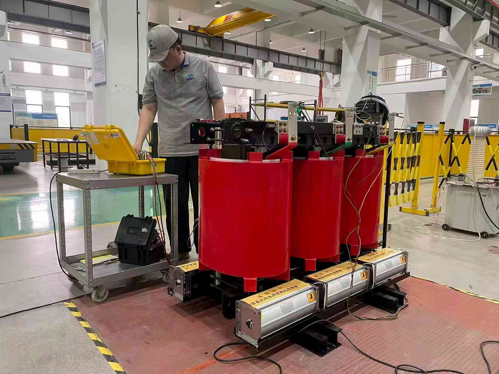
Dry-type transformers hold an unusual place in power distribution. They are rarely the most eye-catching item in a substation, yet they are often the last barrier between the utility supply and a building full of people, sensitive electronics, or a production line that cannot tolerate an outage. Unlike oil-filled units, they replace mineral oil — the familiar cooling and insulating medium — with air and solid insulation, usually cast resin or vacuum-pressure-impregnated paper. That single difference shapes everything downstream: fire performance, environmental compliance, and above all, how the transformer is tested during its life.
Testing is not one event. It is a layered process that starts before the unit leaves the factory and continues through commissioning and periodic maintenance. Which tests apply depends on the design, the voltage class and the governing standard — most commonly IEC 60076-11 or IEEE C57.12.01. Whatever the standard, the tests fall into three groups: routine tests that every unit must pass, type tests that qualify a design, and special tests that address specific duties or concerns.
- Routine Tests — The Non-Negotiables
Routine tests are carried out on every transformer before shipment. They are the baseline evidence that the unit was built correctly and behaves as intended. The list below follows IEC 60076-11 and is mirrored in the IEEE standards.
| Test | What it checks | Typical acceptance criterion |
| Winding resistance | Conductor continuity, joint quality, correct tap connections | Measured at every tap; deviation between phases within a few percent |
| Voltage ratio and phase displacement | That the unit delivers the ordered voltage, and that the vector group (e.g. Dyn11) is correct for paralleling | Measured at every tap; ratio within IEC 60076-1 tolerance (typically ±0.5%) |
| Short-circuit impedance and load loss | Fault-current limitation, load sharing, and I²R plus stray losses | Impedance within ±10% of the guaranteed value; load loss within guarantee |
| No-load loss and no-load current | Quality of the core steel, tightness of core clamping, magnetizing current | Within guarantee; commonly +15% tolerance on no-load loss |
| Separate-source AC withstand (AV) | Integrity of the main insulation to earth and between windings | One minute at the specified test level with no breakdown |
| Induced AC withstand (IV / ACSD) | Turn-to-turn and layer-to-layer insulation, which the separate-source test does not fully stress | No breakdown at the induced test level |
| Partial discharge (PD) | Voids, delamination or weak spots inside cast-resin insulation | Typically ≤ 10 pC for cast-resin designs |
| Insulation resistance and polarization index | Moisture content and general condition of the insulation system | Ratio and absolute values per IEEE 43 or the manufacturer’s limit |
Two of these deserve a note. Impedance and load loss are measured by short-circuiting one winding and applying reduced voltage to the other, then deriving impedance from voltage, current and power — the result governs how the transformer behaves under fault conditions and how well it shares load with its neighbours. No-load loss and current are measured with one winding energised at rated voltage and the other open; the power drawn is essentially core loss, and it is the clearest indicator of core steel quality. A unit with abnormally high no-load loss runs hotter and costs more every year it is in service.
Partial discharge deserves particular attention on dry-type units. PD consists of microscopic discharges inside voids or at insulation edges; it is both a symptom and a cause of degradation. A transformer can pass a withstand test and still carry a PD defect that will fail later in service. For cast-resin designs the accepted limit is low — around 10 pC or less — which is why PD measurement has become standard rather than optional.
The sequence closes with insulation resistance measurement, often with a polarization index calculation to detect moisture, plus insulation checks and functional tests on accessories: temperature sensors, fans, and tap changers where fitted.
- Type Tests — Proving the Design
Type tests are not run on every unit. They are performed on a representative sample to demonstrate that a design meets specified performance, and production units of a qualified design are not normally re-tested.
The most demanding is the temperature-rise test. It matters more for dry-type transformers than for any other type, because insulation life is tied directly to operating temperature. The unit is run at rated load — sometimes at a specified overload — until thermal equilibrium is reached, which can take many hours. Winding temperature is measured with embedded sensors or by the resistance method, in which the rise in winding resistance is converted into an average winding temperature. The rise must stay within the limit for the insulation class — for example 100 K for class F at rated conditions. The test validates both the thermal design and the cooling arrangement.
The lightning impulse test is the second pillar, although for critical applications it is sometimes applied as a routine test. A standard 1.2/50 µs waveform is applied to each high-voltage terminal and the resulting voltage and current traces are recorded. Any deviation from the expected waveform — a sudden collapse in voltage, for instance — indicates breakdown somewhere in the winding. Impulse testing is more demanding on dry-type designs, because solid insulation behaves differently from oil, but it remains the best evidence of surge withstand capability.
Sound-level determination has grown in importance as dry-type transformers move closer to occupied space. A unit humming at 65 dB in a dedicated electrical room is one thing; the same unit beside a hospital ward or an open-plan office is another. Sound pressure is measured at defined points around the transformer at rated voltage, both to confirm the guaranteed level and to expose abnormal noise sources.
- Special Tests — When the Standard Is Not Enough
Special tests are neither routine nor universally required. They are performed when the purchaser specifies them, when the application demands it, or when routine and type testing leave a question unanswered.
Short-circuit withstand is the most severe. One winding is short-circuited while rated voltage is applied to the other; the resulting currents are many times rated current, and the electromagnetic forces inside the windings are enormous. The test proves that the windings and their support structure survive without deformation or insulation damage. It is especially relevant to dry-type units, because solid insulation has none of oil’s self-healing behaviour. A winding that shifts slightly under short-circuit forces may not fail immediately, but the mechanical stress it leaves in the insulation leads to premature failure.
Frequency response analysis (FRA) has become a standard diagnostic for mechanical integrity. A range of frequencies is injected into one winding and the response measured at another, producing a signature that reflects the physical geometry of windings and core. Compared against a factory or previous baseline, that signature reveals winding deformation, core movement or other mechanical changes invisible to conventional electrical tests. FRA is particularly valuable after a through-fault or after rough handling in transport.
Where a unit is destined for a harsh or unusual environment, climatic, environmental and fire-behaviour tests may be specified. IEC 60076-11 defines the classifications below.
WeChat
Scan the QR Code with wechat